Drone Surveying
This is with reference to a Real World Project (Example Project)
Step 1 – Identify the surveying requirements
- Identify accuracy required
- Confirm if Global or Relative accuracy is required
- Evaluate if Drone Technology is suitable
- If Drone Technology is not suitable – use traditional methods, total station and GPS Rover.
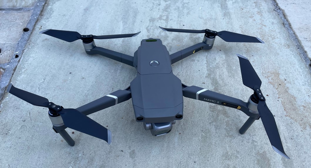
Project Example – Accuracy required in Example project was +/- 50mm. This determined the most suitable flight height. Drone was suitable and there were no flight restrictions / approvals required. Drone used was a Mavic 2 Pro and the site area was c.60Acres – with total flight covering 90 Acres.
Step 2 – Prepare Flight Plan
- Flight plan height to be determined, generally this is between 30m and 120m.
- The lower the height the more detail will be captured on the photos – however more photos will be required. This results in a longer processing time and longer flight time.
- The Ground Sampling Distance (GDS) is important here – GSD is measured in centimeters per pixel (cm/px) and is the distance between the centre of 2 pixels on the surface.
- Generally between 1cm and 2cm GSD is sought.
- Horizontal accuracy is generally 2 x GSD and Vertical accuracy is generally 3 x GSD.
- We mostly use Pix4D Capture for flight planning.
Project Example – Flight Plan covered c. 90 Acres, flown at height of 119m (AGL). Flight time was c.31mins (total time 40mins allowing for 1 battery change) and GDS was 3.01cm.
Step 3 – Fly the Site
- Sometimes IAA approval is required (depending on location and height) – we complete the necessary paperwork & submissions on this. We have extensive experience in this area.
- Safety – Risk assessments are completed.
- The flight plan is uploaded to the Drone and flown.
- Photos are captured in Nadir (90 Degrees facing down) and angled – depending on requirements.
- Images have between 60% and 80% overlap.
Project Example – No external approvals were required. 454 images were taken and processed and mission was complete in 70mins allowing for set up / risk assessments & 1 battery change.
Step 4 – Process the Images
- The images are loaded into Photogrammetry software – such as Pix4D Mapper
- Ground Control Points (GCPs) are added (if necessary – this depends on the drone used and the accuracy required).
- GCPs are usually surveyed using GPS Rover on points identifiable in the photos. Black/White markers are generally used for this.
- The images are processed and the outputs generated.
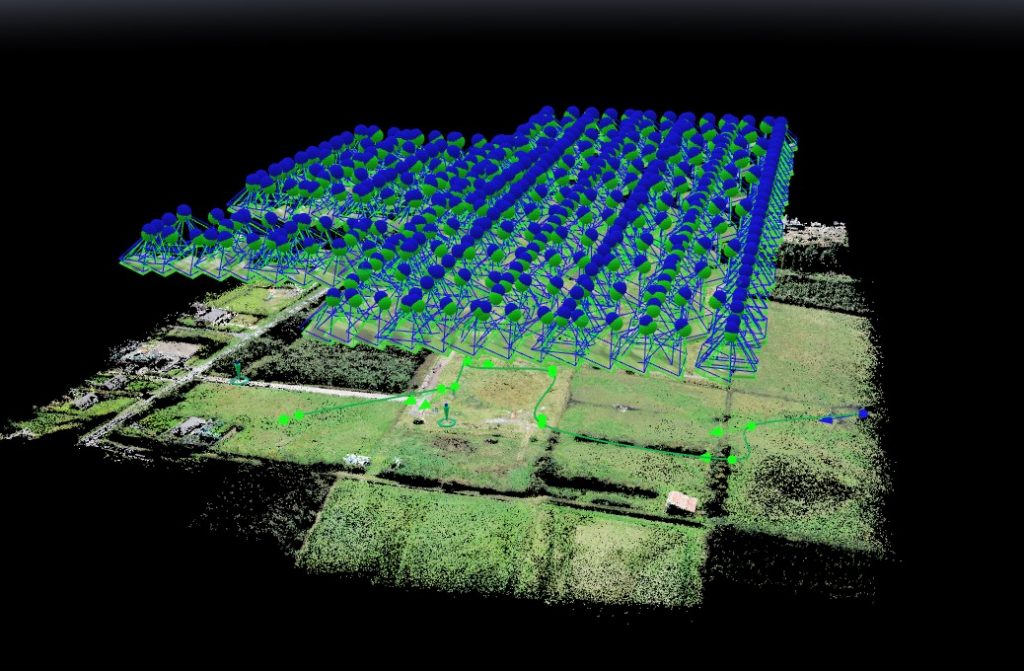
- A Ray Cloud and a Point Cloud is produced.
Project Example – 6 GCPs were used to ensure Global accuracy and 2 Check Points were used to measure accuracy. These were all surveyed with a Leica GPS Rover.
Step 5 – Outputs
- The following outputs are provided;
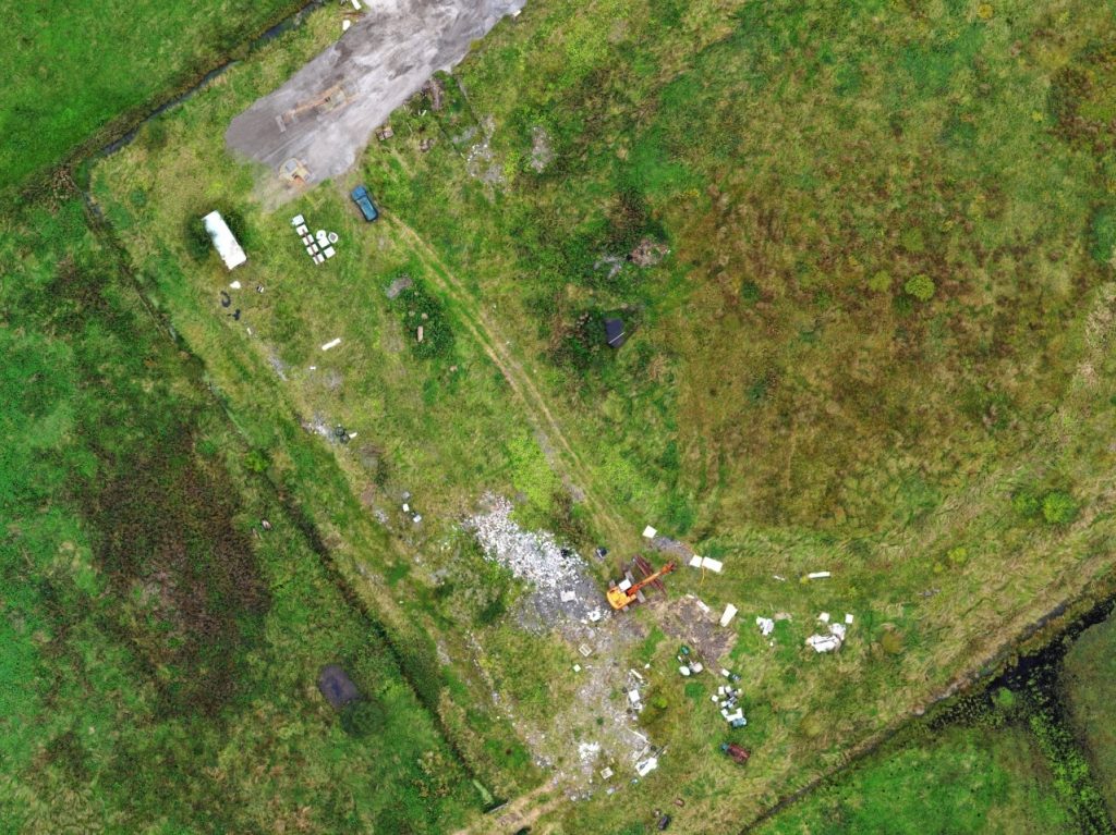
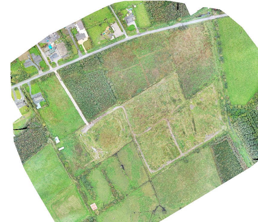
- 2D Orthomosaic Photo (corrected for distortion and measurements can be taken directly from this)
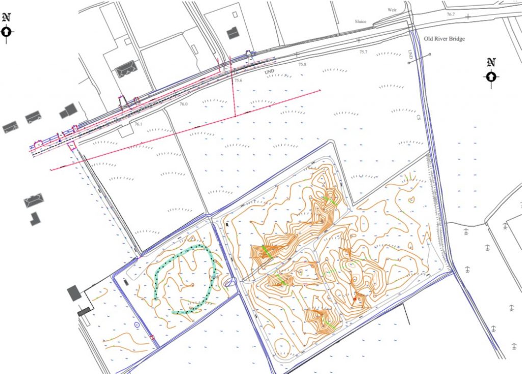
- AutoCAD digitised drawing (site plan) with spot levels as required.
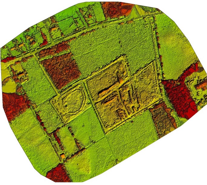
- Contours showing elevation in relative or actual elevations
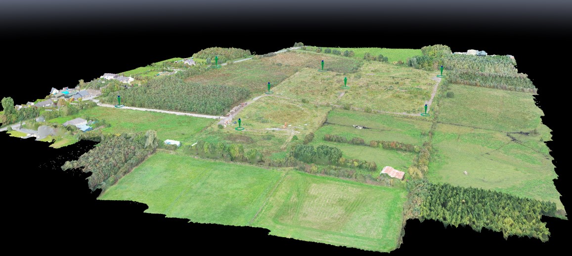
- A 3D computer generated model of the site.
Project Example – See below Typical outputs for this project